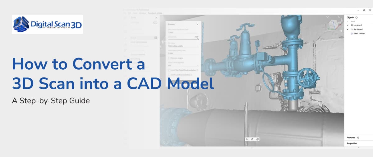
One of the most common goals of 3D scanning is transforming a physical object into an editable CAD model. This process, commonly known as scan-to-CAD, is widely used in reverse engineering, product development, manufacturing, and quality control.
While capturing a scan is relatively straightforward, creating a usable CAD model requires several important steps.
Why Convert a 3D Scan into CAD?
A scan typically produces a mesh file containing millions of data points that represent an object’s surface.
However, engineering workflows often require:
- Parametric CAD models
- Manufacturing drawings
- Design modifications
- CNC machining data
- Product development files
Converting the mesh into CAD geometry allows engineers to work with editable models rather than static scan data.
Step 1: Capture the Object
The workflow begins with scanning the physical object.
The scanner should be selected based on:
- Object size
- Required accuracy
- Surface complexity
- Project goals
Popular reverse engineering scanners include Artec Leo, Artec Space Spider, and Artec Micro.
Step 2: Process the Scan Data
Once scanning is complete, the data must be cleaned and optimized.
Using Artec Studio, users typically perform:
- Scan alignment
- Noise removal
- Mesh fusion
- Hole filling
- Surface optimization
The result is a high-quality mesh suitable for engineering workflows.
Step 3: Refine the Mesh
In many projects, additional mesh editing improves the quality of the data.
Geomagic Wrap is commonly used to:
- Repair mesh defects
- Remove unwanted geometry
- Simplify large datasets
- Improve mesh quality
This step helps ensure smooth CAD reconstruction later in the process.
Step 4: Import the Mesh into Geomagic Design X
Once the mesh is finalized, it can be imported into Geomagic Design X.
Design X specializes in converting mesh data into CAD geometry.
The software provides tools for:
- Feature extraction
- Surface reconstruction
- Sketch creation
- Parametric modeling
Step 5: Build the CAD Model
Engineers use Design X to identify important features such as:
- Holes
- Planes
- Cylinders
- Curves
- Complex surfaces
These features become the foundation of the final CAD model.
Unlike the original mesh, the resulting model can be modified and used in engineering applications.
Step 6: Export to CAD Software
The completed CAD model can be exported to engineering platforms for further development.
Common uses include:
- Product redesign
- Manufacturing
- Tooling
- Simulation
- Documentation
This creates a seamless connection between physical objects and digital engineering workflows.
Common Applications
Organizations use scan-to-CAD workflows for:
Reverse Engineering
Recreating obsolete or undocumented parts.
Product Development
Improving existing products without starting from scratch.
Manufacturing
Creating production-ready models and drawings.
Quality Control
Comparing manufactured parts against original CAD designs.
Benefits of Scan-to-CAD Workflows
- Faster development cycles
- Reduced manual measurements
- Improved accuracy
- Better collaboration
- More efficient redesign processes
These advantages have made scan-to-CAD an essential tool across numerous industries.
Final Thoughts
Converting a 3D scan into a CAD model involves more than simply capturing geometry. A successful workflow requires proper scan processing, mesh preparation, and CAD reconstruction. By combining Artec Studio, Geomagic Wrap, and Geomagic Design X, organizations can efficiently transform physical objects into editable CAD models, accelerating reverse engineering and product development projects while maintaining accuracy and reliability.